
Free Delivery  ·  COD Available  ·  15-Day Returns
Pricio
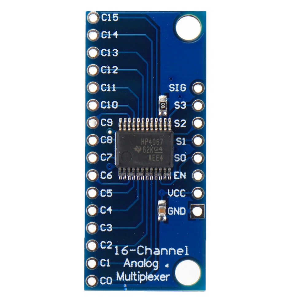
Smart Electronics CD74HC4067 16-Channel Analog Digital Multiplexer PCB Board Module — image 1
Hover to zoom

Smart Electronics CD74HC4067 16-Channel Analog Digital Multiplexer PCB Board Module

5.032 ratings
741+ bought in past month
AI Summary
product for everyday users

The Smart Electronics CD74HC4067 16-Channel Analog Digital Multiplexer PCB Board Module is a value-for-money product designed for everyday users. Customers praise its easy to set up and use and fast and responsive. 100% of buyers rate it 4★ or above.

easy to set up and usefast and responsiveaccurate and reliable
₹620
Free Shipping💵 COD Available

Available Offers

Free Delivery on this order. No minimum order value.

15-Day Easy Returns — hassle-free return & full refund.

Secure Payment — 100% safe checkout with UPI, Cards & Net Banking.

Total: ₹620
Buying tip: A smart budget buy — solid performance without breaking the bank.
Estimated delivery: 17 Aug31 Aug
Free Shipping
Pan India delivery
15-Day Returns
Hassle-free policy
Secure Payment
Razorpay protected
Quality Assured
Vetted products only

Available Offers

💳

5% Cashback

Pay with UPI & get 5% cashback (up to ₹50) via Razorpay

🏦

No-Cost EMI

Available on select bank cards at checkout. 0% interest for 3 months.

📦

Free Shipping

Free delivery on all orders. No minimum order value.

💵

Cash on Delivery

COD available on orders up to ₹5,000 across India.

Ideal For

Everyday convenience
Share:
SKU: bg-1595114

About This Product

The Smart Electronics CD74HC4067 16-Channel Analog Digital Multiplexer PCB Board Module is a value-for-money designed for everyday users. Customers highlight its easy to set up and use and fast and responsive.

Customer Verdict

100% of buyers rated this product 4 stars or above. The most appreciated qualities are: easy to set up and use, fast and responsive, accurate and reliable.

Why Buy from Pricio?

Pricio sources this product directly, cutting out multiple middlemen. Every order includes free shipping, a 15-day return policy, and secure payment via Razorpay.

Specifications:
1. 2V to 6V operation 
2. "On" resistance: 70 Ohms @ 4.5V 
3. 6ns break-before-make @ 4.5V 
4. Wide operating temperature range: -50℃ to 125℃
Features:
- This is a break board for the very handy 16-Channel Analog/Digital Multiplexer/Demultiplexer CD74HC4067.
- This chip is like a rotary switch - it internally routes the common pin to one of 16 channel pins (CHANxx).
- It works with both digital and analog signals (the voltage can't be higher than VCC),and the connections function in either direction.
- To control it, connect 4 digital outputs to the chip's address select pins (S0-S3),and send it the binary address of the channel you want.
- This allows you to connect up to 16 sensors to your system using only 5 pins!
- You can use it to pipe TTL-level serial data to or from multiple devices.

For example, you could use it to connect the TX pins of 16 devices to one RX pin on your microcontroller.
You can then select any one of those 16 devices to listen to.
If you want two-way communications, you can add a second board to route your microcontroller's TX line to 16 device's RX lines. 
By using multiple boards, you can create similar arrangements for I2C, SPI, etc. 
The internal switches are bidirectional, support voltages between ground and VCC, have low "on" resistance and low "off" leakage, and to prevent crosstalk, perform "break-before-make" switching.
The board also breaks out the chip's "enable" pin, which when driven high, will completely disconnect the common pin (all switches "off").

Package Included:
1 x CD74HC4067 16-Channel Analog Digital Multiplexer


Product Safety Information

Setup Guide

1
Identify the pins
Locate VCC (power), GND (ground), and data pins (SDA/SCL for I2C, MOSI/MISO for SPI, or TX/RX for UART). Refer to the pinout diagram on the product page.
2
Wire to your microcontroller
Connect VCC to 3.3V or 5V (check the module spec), GND to GND, and data pins to the appropriate GPIO pins on your Arduino or Raspberry Pi.
3
Install libraries
In Arduino IDE, go to Sketch → Include Library → Manage Libraries and search for the sensor library. Install the recommended version.
4
Upload example sketch
Open File → Examples → [library name] → Basic Example. Upload to your board and open Serial Monitor to view output.
5
Calibrate if needed
Some sensors (temperature, humidity, distance) may need a short warm-up period or calibration. Run the calibration sketch if provided.