
1 / 6 · Click to enlarge
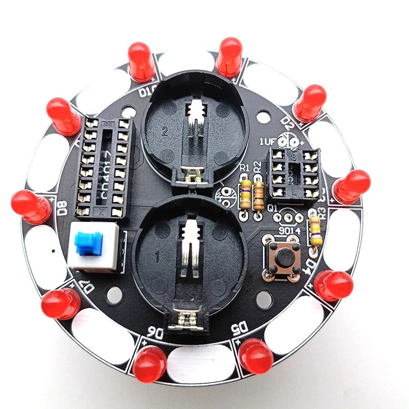
Lucky Turntable LED Flashlight DIY Electronic kit Welding Project Training Module DIY Kit
5.01 ratingThe Lucky Turntable LED Flashlight DIY Electronic kit Welding Project Training Module DIY Kit is a value-for-money product designed for DIY enthusiasts and makers. Customers praise its fast and responsive.
Available Offers
Free Delivery on this order. No minimum order value.
15-Day Easy Returns — hassle-free return & full refund.
Secure Payment — 100% safe checkout with UPI, Cards & Net Banking.
19% Off — you save ₹160 on this product!
Price: ₹685
Available Offers
5% Cashback
Pay with UPI & get 5% cashback (up to ₹50) via Razorpay
No-Cost EMI
Available on select bank cards at checkout. 0% interest for 3 months.
Free Shipping
Free delivery on all orders. No minimum order value.
Cash on Delivery
COD available on orders up to ₹5,000 across India.
Ideal For
About This Product
The Lucky Turntable LED Flashlight DIY Electronic kit Welding Project Training Module DIY Kit is a value-for-money designed for DIY enthusiasts and makers. Customers highlight its fast and responsive.
Why Buy from Pricio?
Pricio sources this product directly, cutting out multiple middlemen. Every order includes free shipping, a 15-day return policy, and secure payment via Razorpay.
Description:
Function play: the lucky wheel is a tool to predict where the rotating disc will stop when it stops. It can also be used as number estimation games, electronic dice, lottery machines, etc. The electronic lucky wheel achieves the same function by electronic means. In this kit, 10 LEDs are configured into a circle. When the power switch is turned on and the start button is pressed, each LED lights up in turn. At first, the flow speed is very fast. It seems that all LEDs flash together, and the flow speed will become slower and slower. Finally, it stops at a certain LED and does not move. If the last LED is the same as the player's prediction, it means "winning the prize".
Circuit principle: The circuit is mainly composed of pulse generator and a decimal counter circuit. The pulse generator is a multivibrator composed of NE555 and peripheral components. When the key S1 is pressed, Q1 is turned on, and the three pins of NE555 output pulses, then the ten output terminals of CD4017 output high level in turn to drive ten LEDs to emit light in turn. After the key is released, Q1 will not be turned off immediately because of the existence of the capacitor C2. With the decrease of the voltage across C2, the turn-on procedure of Q1 will gradually weaken, the frequency of the three-pin output pulse will slow down, and the LED moving frequency will also slow down. Finally, when C2 discharge is over. Q1 turns off, the 3 pins of NE555 no longer output pulses, and the LED stops moving. A "lottery" process is thus completed. R2 determines the moving speed of the LED, and C2 determines the waiting time for the lottery.
Parameters:
Power supply voltage: 6V
Overall dimensions: diameter 68.8MM
Weight of parts: 32.5g
Package Include:
【Module】:
1x Lucky Turntable (Finished)
【Parts】:
1x PCB board
1x 8*8 self-locking switch
1x 8*8 cap
1x 6*6*5 key
1x 1UF capacitor 50V
1x 100UF25V capacitor
11x 5MM LED red
2x CR2032 battery holder
2x CR2032 battery
2x 470K resistor
1x 10K resistor
1x 9014 triode
1x 8-pin IC block
1x NE555
1x 16 pin IC base
1x CD4017


