
1 / 7 · Click to enlarge
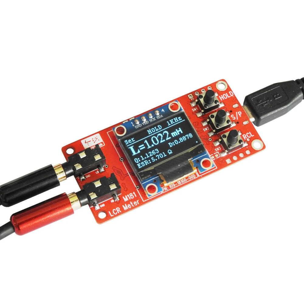
Jyetech M181 LCR Meter 18101K DIY Kit 100Hz 1KHz Test Frequency High-precision Small Value Inductance Resistance and Capacitance Measurement Module
5.04 ratingsThe Jyetech M181 LCR Meter 18101K DIY Kit 100Hz 1KHz Test Frequency High-precision Small Value Inductance Resistance and Capacitance Measurement Module is a mid-range product designed for DIY enthusiasts and makers. Customers praise its fast and responsive and compact and portable.
Available Offers
Free Delivery on this order. No minimum order value.
15-Day Easy Returns — hassle-free return & full refund.
Secure Payment — 100% safe checkout with UPI, Cards & Net Banking.
Available Offers
5% Cashback
Pay with UPI & get 5% cashback (up to ₹50) via Razorpay
No-Cost EMI
Available on select bank cards at checkout. 0% interest for 3 months.
Free Shipping
Free delivery on all orders. No minimum order value.
Cash on Delivery
COD available on orders up to ₹5,000 across India.
Ideal For
About This Product
The Jyetech M181 LCR Meter 18101K DIY Kit 100Hz 1KHz Test Frequency High-precision Small Value Inductance Resistance and Capacitance Measurement Module is a mid-range designed for DIY enthusiasts and makers. Customers highlight its fast and responsive and compact and portable.
Why Buy from Pricio?
Pricio sources this product directly, cutting out multiple middlemen. Every order includes free shipping, a 15-day return policy, and secure payment via Razorpay.
Introduction:
M181 LCR meter is a practical kit for measuring the R, C, or L of either through-hole or surface-mount components. It features about 1% accuracy, which is adequate in most engineering scenarios. Not only being very easy to build, it also includes a Self Test mode that helps users to verify the correctness of assembly. Compact in size and the capability of serial output make the meter a great choice for many embedded applications.
Highlights of M181 LCR Meter:
Resistance range: 0.1ohm — 10M ohm
Capacitance range: 1pF — 10000uF
Inductance range: 1uH — 20H
Fully automatic ranging
Accuracy: about 1%
Measurement frequency: 1KHz/100Hz selectable
Measurement voltage: 0.6Vpp
Built-in virtual USB comport for data output and firmware upgrade
Serial data output via USB comport or direct LVTTL
Display HOLD function
USB (5V) powered
Easy to build, easy to use
Self test mode for verifying the correctnes of assembly
Acrylic panels included
Specifications:
Display:
Primary: R, C, L
Secondary: Q, D, ESR
Equivalent Circuit Mode: Parallel or Serial
Measurement Range and Accuracy:
R, |Z|: 0.1Ω - 10MΩ
C: 1pF - 10000μF
L: 1μH - 20H
Q, D: 0 - 10000
Accuracy: About 1%
Measurement Conditions:
Test Frequency: 100Hz, 1KHz
Open Voltage: 0.6Vpp
Miscellaneous:
Measurement Connections: 4 Kelvin wires on the test terminals
Ranging: Fully automatic
Compensations: Open, Short
Serial Data Output: Yes
Power Supply: USB
Power Consumption: < 100mA @ 5V
Dimensions: 66 x 32x 19mm (2.60" x 1.26" x 0.75")
Weight: 23g (76g with probes)
Documents:
M181 User Manual
M181 Assembly Guide
Schematic
Component Locations
Package includes:
1x M181 LCR Meter DIY kit


