
1 / 11 · Click to enlarge
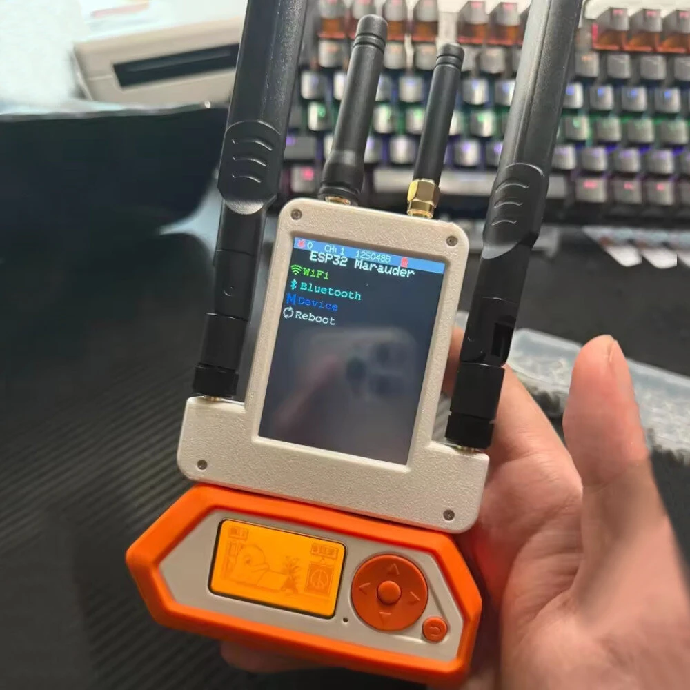
4 in 1 Expansion Board 433M RF +ESP32S2 + GPS + 2.8 inch Screen Module with 4pcs Antenna For Flipper Zero
5.015 ratingsThe 4 in 1 Expansion Board 433M RF +ESP32S2 + GPS + 2.8 inch Screen Module with 4pcs Antenna For Flipper Zero is a premium product designed for premium buyers. Customers praise its fast and responsive. 100% of buyers rate it 4★ or above.
Available Offers
Free Delivery on this order. No minimum order value.
15-Day Easy Returns — hassle-free return & full refund.
Secure Payment — 100% safe checkout with UPI, Cards & Net Banking.
30% Off — you save ₹2,673 on this product!
Type: With Shell
Available Offers
5% Cashback
Pay with UPI & get 5% cashback (up to ₹50) via Razorpay
No-Cost EMI
Available on select bank cards at checkout. 0% interest for 3 months.
Free Shipping
Free delivery on all orders. No minimum order value.
Cash on Delivery
COD available on orders up to ₹5,000 across India.
Ideal For
About This Product
The 4 in 1 Expansion Board 433M RF +ESP32S2 + GPS + 2.8 inch Screen Module with 4pcs Antenna For Flipper Zero is a premium designed for premium buyers. Customers highlight its fast and responsive.
Customer Verdict
100% of buyers rated this product 4 stars or above. The most appreciated qualities are: fast and responsive.
Why Buy from Pricio?
Pricio sources this product directly, cutting out multiple middlemen. Every order includes free shipping, a 15-day return policy, and secure payment via Razorpay.
Note: Due to version upgrade issues and different production batches, you may receive a different version. Appearance and functionality may vary. Please refer to the version you receive. (All the versions sent out from October are new versions.)
Before update:
Features:
1. It consists of 433M RF module + ESP32S2 module + GPS module + 2.8-inch , 4 in 1
2. The GPS module can be shared with Flipper Zero and 2.8-inch, and the power supply method is optional
3. The RF module can enter the subghz menu and select the external module for direct use
4. The S2 module can be used in the WiFi in the GPIO menu in the APP
5. The S2 module uses the 15 and 16 pins of Flipper Zero, and each signal pin is equipped with TVS
After update:
Features:
1. 4-in-1 design consisting of a 433M RF module, an ESP32S2 module, a GPS module, and a 2.8-inch screen.
2. The GPS module can be used with both the Flipper Zero and the 2.8-inch, automatically switching to be powered by the Flipper Zero without manual switching.
3. The RF module can be used directly by selecting the external module in the subGHz menu.
4. The S2 module can be used with the WiFi in the GPIO menu of the app.
5. The S2 module uses Flipper Zero pins 15 and 16, and each signal pin has a TVS.
6. The GPS module has been de-modulated in favor of a fully surface mount design, resulting in a more compact design with improved signal quality and a more compact design.
7. Both the ESP32 module and the ESP32-S2 module can be flashed using the USB port.
Product parameters:
Battery capacity: 800mAh
Antenna specifications: 2.4Ghz is 3dbi antenna, GPS is 20dbi antenna, 433M is 3dbi antenna
Package includes:
1 x 4in1 Module
4 x Antenna
(the Flipper Zero is not includes)


