
Free Delivery  ·  COD Available  ·  15-Day Returns
Pricio
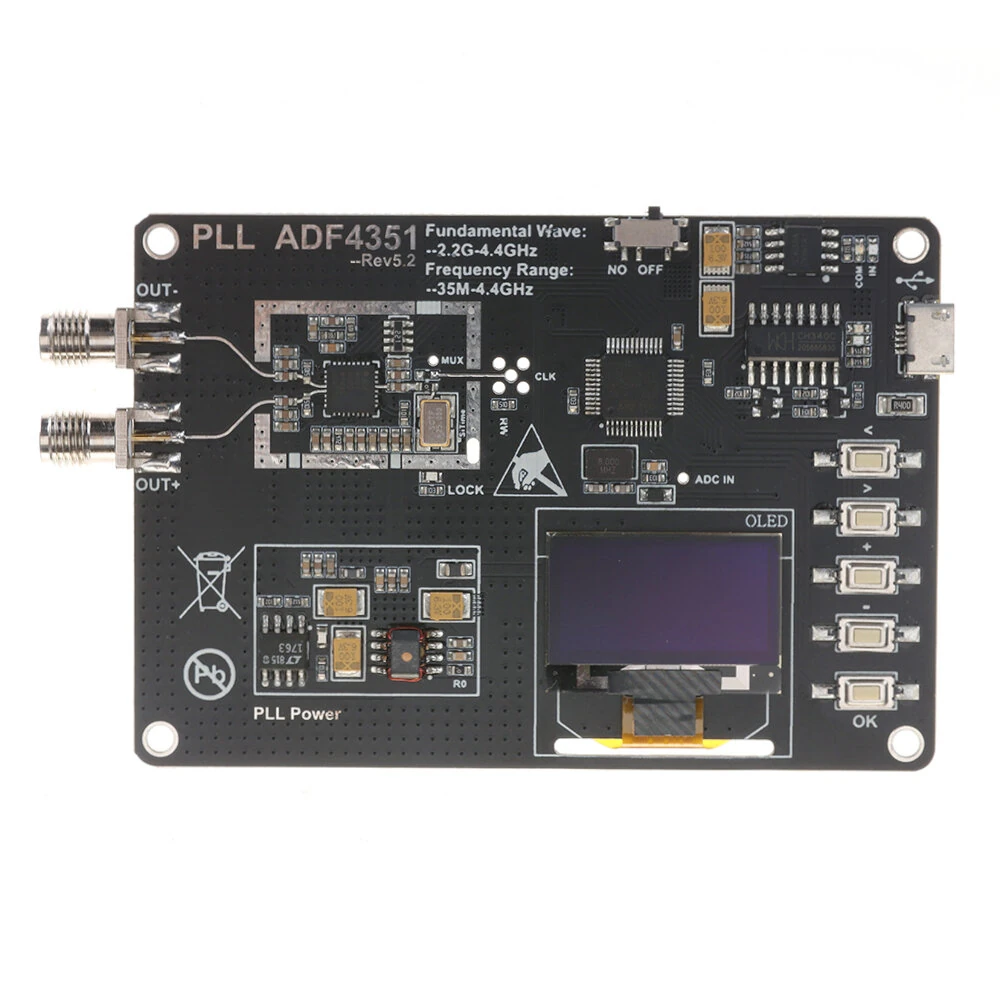
35MHz-4400MHz RF Signal Generator ADF4351 Module Sweep Frequency Generator PLL With OLED Display — image 1
Hover to zoom

1 / 9 · Click to enlarge

35MHz-4400MHz RF Signal Generator ADF4351 Module Sweep Frequency Generator PLL With OLED Display

21+ bought in past month
AI Summary
Test & Measuring Module for everyday users

The 35MHz-4400MHz RF Signal Generator ADF4351 Module Sweep Frequency Generator PLL With OLED Display is a mid-range test & measuring module designed for everyday users.

₹4,792-35%
MRP:₹7,402Save ₹2,610
Free Shipping💵 COD Available

Available Offers

Free Delivery on this order. No minimum order value.

15-Day Easy Returns — hassle-free return & full refund.

Secure Payment — 100% safe checkout with UPI, Cards & Net Banking.

35% Off — you save ₹2,610 on this product!

Type: Without Battery

Without Battery
Total: ₹4,792
Buying tip: A quality investment for dependable performance and premium build quality.
Estimated delivery: 21 Aug4 Sept
Free Shipping
Pan India delivery
15-Day Returns
Hassle-free policy
Secure Payment
Razorpay protected
Quality Assured
Vetted products only

Available Offers

💳

5% Cashback

Pay with UPI & get 5% cashback (up to ₹50) via Razorpay

🏦

No-Cost EMI

Available on select bank cards at checkout. 0% interest for 3 months.

📦

Free Shipping

Free delivery on all orders. No minimum order value.

💵

Cash on Delivery

COD available on orders up to ₹5,000 across India.

Ideal For

Electronics projectsArduino / Raspberry Pi buildsPrototyping
Share:
SKU: bg-2042441Category: Test & Measuring Module

About This Product

The 35MHz-4400MHz RF Signal Generator ADF4351 Module Sweep Frequency Generator PLL With OLED Display is a mid-range test & measuring module designed for everyday users. It delivers reliable performance at an accessible price.

Why Buy from Pricio?

Pricio sources this product directly, cutting out multiple middlemen. Every order includes free shipping, a 15-day return policy, and secure payment via Razorpay.

Features:
- Four-layer PCB process, digital circuit and analog circuit separation.
- Supports battery and USB powered. (The battery is not included in the shipping list. Please prepare and solder the battery for it by yourself.)
- Metal-shielded RF circuits.
-High brightness OLED display.
- With CH340C serial chip, serial communication and firmware download can be realized.
- Five-way navigation button, easy to operate.
- Programmable SiTime crystal oscillator, reserved for external clock.

Description:
The main control adopts STM32F103C8T6, fractional N divider frequency synthesizer and integer N divider frequency synthesizer PLL-ADF4351 PLL. The output frequency range is 35m-4400MHz. The main board adopts four-layer gold precipitation process, excellent component selection, classic layout and wiring PCB design, making the signal output extremely stable, phase noise to meet the official design requirements. On-board 25MHz active SiTime crystal oscillator, and reserved external clock interface, MCU ADC interface. Simple five-key operation design, clear logics, can set the point frequency, sweep mode output, sweep frequency step and sweep cycle can be adjusted. The mainboard can be powered by battery and USB. The charging current is 1A when the battery is used. In addition, USB can be connected to the computer through serial port for communication and downloading programs.

Specification:
- Size: 85mm * 58mm
- USB5V or 4.2V Battery. The battery is not included in the shipping list. Please prepare and solder the battery for it by yourself.
- Bandwidth: 35MHz-4.4GHz (35MHz-4400MHz).
- Dual channel differential output Out -& Out +
- Module step: 100KHz (minimum)
- Frequency error: ±1KHz
- Module phase noise: better than -100dBc at 10KHz (noise varies with the frequency band phase)
- Module output power: 10dBm (maximum)
- Module phase noise: better than -100dBc at 10KHz (noise varies with the frequency band phase)
- Programmable 1/2/4/8/16/32/64 divider output
- Typical RMS jitter: 0.3ps RMS
- VM: 0.4% (typical, 2.1 GHz)

Package Included:
1 x Signal Generator Module


Product Safety Information

Setup Guide

1
Identify the pins
Locate VCC (power), GND (ground), and data pins (SDA/SCL for I2C, MOSI/MISO for SPI, or TX/RX for UART). Refer to the pinout diagram on the product page.
2
Wire to your microcontroller
Connect VCC to 3.3V or 5V (check the module spec), GND to GND, and data pins to the appropriate GPIO pins on your Arduino or Raspberry Pi.
3
Install libraries
In Arduino IDE, go to Sketch → Include Library → Manage Libraries and search for the sensor library. Install the recommended version.
4
Upload example sketch
Open File → Examples → [library name] → Basic Example. Upload to your board and open Serial Monitor to view output.
5
Calibrate if needed
Some sensors (temperature, humidity, distance) may need a short warm-up period or calibration. Run the calibration sketch if provided.