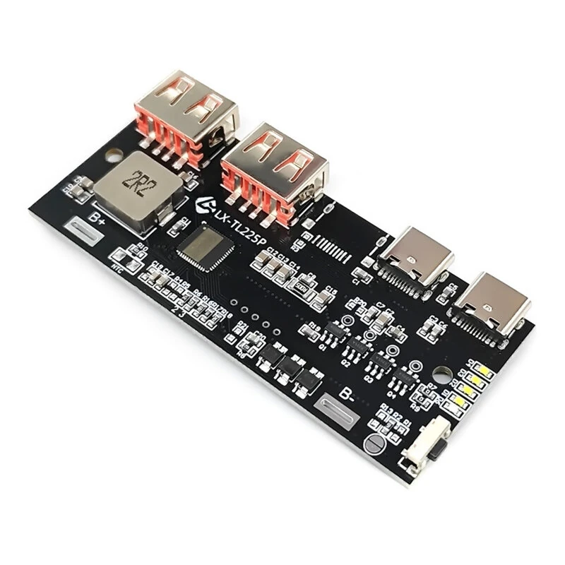
Specifications:
Digital Display:
Input Voltage: 6V-8.4V
Output Voltage: 5V / 3.3V / 12V (max)
Max Output Power: 22.5W
Fast Charging Protocols Supported: BC1.2, QC2.0/3.0/4.0, PD2.0/3.0, PPS, SCP, FCP, AFC, VOOC, DASH, WARP, PE2.0/PE1.1, SFCP
Ports: 2 USB (Fast-charging), 2 Type-C
Display: LED percentage digital screen
LED Lamp:
Input Voltage: 5–12V
Output Power: Up to 22.5W
Supported Fast Charging Protocols: BC1.2, 5V2.4A, AFC, PD2.0/3.0/PPS, FCP, QC2.0/3.0/4.0, SCP, VOOC/DASH/WARP, PE2.0/PE1.1, SFCP
Ports: USB-A and USB-C
LED Display Indicator: Real-time charging status
Features:
1. Wide Compatibility: Supports multiple fast charging protocols for a variety of devices, ensuring efficient power delivery.
2. Advanced Circuit Design: Engineered for stable charging under varying voltage conditions, minimizing heat generation.
3. LED Display: Features a clear, real-time LED indicator for monitoring power output.
4. Compact Build: Lightweight and small design ideal for integration into DIY projects or portable power solution.
5. Dual Charging Ports: Includes USB-C and USB-A outputs, allowing simultaneous charging for multiple devices.
Package Included:
1 x Fast Charging Module Circuit Board
Usage Precautions:
1. After receiving the motherboard, test it by connecting it to the charging head and checking the LED lights. Only assemble it after confirming all lights are on.
2. For normal use, the battery must be soldered (twisted wires will cause insufficient power supply). Reversing the battery connection will burn out the motherboard. The wires must be thick and short.
3. The battery and motherboard wires should not be too thin; they should be as thick as possible. Fast charging boards require a 10A current capacity, and non-fast charging boards should be able to handle at least 7A. They should also not be too long, and the interfaces need to be soldered.
4. Batteries can only be connected in parallel (the number of parallel connections is unlimited), not in series. Series connection will burn out the motherboard.
5. Ensure the battery is good. If the battery fully charges immediately upon connection but cannot discharge when plugged into the phone, it is likely due to battery aging and failure.
6. If the battery has a built-in protection board, ensure the protection current is greater than 7A (greater than 10A for fast charging versions). Otherwise, removing the protection board may cause the output to disconnect after a discharge exceeding one or two amps.
7. Reversing the connection will burn out the board. Burnt IC will leave marks. This only occurs with reverse connection. Therefore, we are not responsible for the consequences of reverse connection. For example, if the protection chip is burned out or detached, or if the main control chip shows obvious burn marks, the damage to the protection chip is 100% a usage problem.
8. When connecting the battery, ensure that it is a 3.2V lithium battery, not other types of batteries. Ensure that the batteries are not connected in series; otherwise, if the voltage at the battery end is higher than 4.5V, it may burn out the board.
9. The board's power indicator has a built-in coulomb counter. The display will be inaccurate when the battery is first connected. The power counter supports a battery capacity self-learning function; it will learn the current battery capacity after several complete charging cycles.
10. There is no truly full-protocol board; we can only say that it supports a wide range of protocols. Because mobile phones are constantly being updated, a board that supports a certain brand of mobile phone today may support a different protocol in a new model tomorrow, resulting in the board not supporting it. For example, Honor phones used to support the 5V 4.5A SCP protocol, but the latest phones only support the 10V 2.5A SCP protocol. Therefore, whether it supports a particular protocol depends on the protocol specified on the board.